|
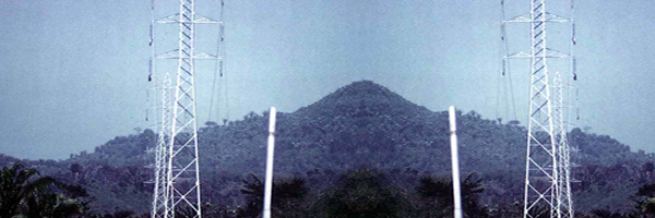
Transmission line are used to transport the energy from power plant to cities and industrial area on high voltage with steel towers design for each load. Voltage depending of the length and power to be transported .
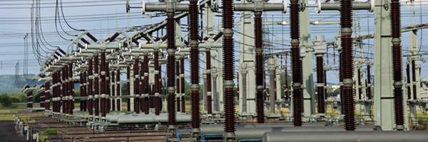
An electrical substation is a subsidiary station of an electricity generation, transmission and distribution system where voltage is transformed from high to low or the reverse using transformers.
Electric power may flow through several substations between generating
plant and consumer, and may be changed in voltage in several steps.
A substation that has a step-up transformer increases the voltage
while decreasing the current, while a step-down transformer decreases
the voltage while increasing the current for domestic and commercial
distribution. The word substation comes from the days before the distribution system became a grid.
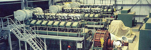
The first substations were connected to only one power station where
the generator was housed, and were subsidiaries of that power station.
Elements of a substation
Substations generally contain one or more transformers, and have
switching, protection and control equipment. In a large substation, circuit breakers are used to interrupt any short-circuits or overload currents that may occur on the network. Smaller
distribution stations may use recloser circuit breakers or fuses for
protection of branch circuits. Substations do not (usually) have
generators, although a power plant may have a substation nearby. A typical substation will contain line
termination structures, high-voltage switchgear, one or more power
transformers, low voltage switchgear, surge protection, controls,
grounding (earthing) system, and metering. Other devices such as power factor correction capacitors and voltage regulators may also be located at a substation.
Substations may be on the surface in fenced enclosures, underground,
or located in special-purpose buildings. High-rise buildings may have
indoor substations. Indoor substations are usually found in urban areas
to reduce the noise from the transformers, for reasons of appearance,
or to protect switchgear from extreme climate or pollution conditions.
Where a substation has a metallic fence, it must be properly grounded
(UK: earthed) to protect people from high voltages that may occur
during a fault in the transmission system. Earth faults at a substation
can cause ground potential rise
at the fault location. Currents flowing in the earth's surface during a
fault can cause metal objects to have a significantly different voltage
than the ground under a person's feet; this touch potential presents a hazard of electrocution.
Transmission substation
A transmission substation connects two or more transmission
lines. The simplest case is where all transmission lines have the same
voltage. In such cases, the substation contains high-voltage switches
that allow lines to be connected or isolated for maintenance. A
transmission station may have transformers to convert between two
transmission voltages, or equipment such as phase angle regulators to control power flow between two adjacent power systems.
Transmission substations can range from simple to complex. A small "switching station" may be little more than a bus
plus some circuit breakers. The largest transmission substations can
cover a large area (several acres/hectares) with multiple voltage
levels, and a large amount of protection and control equipment
(capacitors, relays, switches, breakers, voltage and current
transformers).
Distribution substation
A distribution substation transfers power from the
transmission system to the distribution system of an area. It is
uneconomical to directly connect electricity consumers to the
high-voltage main transmission network, unless they use large amounts
of energy; so the distribution station reduces voltage to a value
suitable for local distribution.
The input for a distribution substation is typically at least two
transmission or subtransmission lines. Input voltage may be, for
example, 115 kV,
or whatever is common in the area. The output is a number of feeders.
Distribution voltages are typically medium voltage, between 2.4 and 33 kV depending on the size of the area served and the practices of the local utility.
The feeders will then run overhead, along streets (or under streets,
in a city) and eventually power the distribution transformers at or
near the customer premises.
Besides changing the voltage, the job of the distribution substation
is to isolate faults in either the transmission or distribution
systems. Distribution substations may also be the points of voltage
regulation, although on long distribution circuits (several km/miles),
voltage regulation equipment may also be installed along the line.
Complicated distribution substations can be found in the downtown
areas of large cities, with high-voltage switching, and switching and
backup systems on the low-voltage side. More typical distribution
substations have a switch, one transformer, and minimal facilities on
the low-voltage side.
Collector substation
In distributed generation projects such as a wind farm,
a collector substation may be required. It somewhat resembles a
distribution substation although power flow is in the opposite
direction, from many wind turbines
up into the transmission grid. Usually for economy of construction the
collector system operates around 35 kV, and the collector substation
steps up voltage to a transmission voltage for the grid. The collector
substation also provides power factor correction, metering and control of the wind farm.
Design
The main issues facing a power engineer
are reliability and cost. A good design attempts to strike a balance
between these two, to achieve sufficient reliability without excessive
cost. The design should also allow easy expansion of the station, if
required.
Selection of the location of a substation must consider many
factors. Sufficient land area is required for installation of equipment
with necessary clearances for electrical safety, and for access to
maintain large apparatus such as transformers. Where land is costly,
such as in urban areas, gas insulated switchgear may save money overall. The site must have room for expansion due to
load growth or planned transmission additions. Environmental effects of
the substation must be considered, such as drainage, noise and road
traffic effects. Grounding (earthing) and ground potential rise
must be calculated to protect passers-by during a short-circuit in the
transmission system. And of course, the substation site must be
reasonably central to the distribution area to be served.
Layout
Tottenham Substation, set in wild parkland in North London
The first step in planning a substation layout is the preparation of a one-line diagram
which shows in simplified form the switching and protection arrangement
required, as well as the incoming supply lines and outgoing feeders or
transmission lines. It is a usual practice by many electrical utilities
to prepare single-line diagrams with principal elements (lines,
switches, circuit breakers, transformers) arranged on the page
similarly to the way the apparatus would be laid out in the actual
station.
Incoming lines will almost always have a disconnect switch and a circuit breaker.
In some cases, the lines will not have both; with either a switch or a
circuit breaker being all that is considered necessary. A disconnect
switch is used to provide isolation, since it cannot interrupt load
current. A circuit breaker is used as a protection device to interrupt
fault currents automatically, and may be used to switch loads on and
off. Where a large fault current flows through the circuit breaker this
may be detected through the use of current transformers. The magnitude
of the current transformer outputs may be used to 'trip' the circuit
breaker resulting in a disconnection of the load supplied by the
circuit break from the feeding point. This seeks to isolate the fault
point from the rest of the system, and allow the rest of the system to
continue operating with minimal impact. Both switches and circuit
breakers may be operated locally (within the substation) or remotely
from a supervisory control center.
Once past the switching components, the lines of a given voltage connect to one or more buses. These are sets of bus bars, usually in multiples of three, since three-phase electrical power distribution is largely universal around the world.
The arrangement of switches, circuit breakers and buses used affects
the cost and reliability of the substation. For important substations a
ring bus, double bus or so-called "breaker and a half" setup can be
used, so that the failure of any one circuit breaker does not interrupt
power to branch circuits for more than a brief time, and so that parts
of the substation may be de-energized for maintenance and repairs.
Substations feeding only a single industrial load may have minimal
switching provisions, especially for small installations.
Once having established buses for the various voltage levels,
transformers may be connected between the voltage levels. These will
again have a circuit breaker, much like transmission lines, in case a
transformer has a fault (commonly called a 'short circuit').
Along with this, a substation always has control circuitry needed to
command the various breakers to open in case of the failure of some
component.
Switching function
An important function performed by a substation is switching,
which is the connecting and disconnecting of transmission lines or
other components to and from the system. Switching events may be
"planned" or "unplanned".
A transmission line or other component may need to be deenergized
for maintenance or for new construction; for example, adding or
removing a transmission line or a transformer.
To maintain reliability of supply, no company ever brings down its
whole system for maintenance. All work to be performed, from routine
testing to adding entirely new substations, must be done while keeping
the whole system running.
Perhaps more importantly, a fault may develop in a transmission line
or any other component. Some examples of this: a line is hit by
lightning and develops an arc, or a tower
is blown down by a high wind. The function of the substation is to
isolate the faulted portion of the system in the shortest possible time.
There are two main reasons: a fault tends to cause equipment damage;
and it tends to destabilize the whole system. For example, a
transmission line left in a faulted condition will eventually burn
down, and similarly, a transformer left in a faulted condition will
eventually blow up. While these are happening, the power drain makes
the system more unstable. Disconnecting the faulted component, quickly,
tends to minimize both of these problems.
Railways
Electrified railways also use substations which may also include
rectifier equipment to change alternating current from the utility
power distribution network to direct current for use by traction motors. |